Approximate Location Map
Large Map »
Latitude: 51.3782 / 51°22'41"N
Longitude: -2.3016 / 2°18'5"W
OS Eastings: 379104
OS Northings: 164391
OS Grid: ST791643
Mapcode National: GBR 0QL.DYB
Mapcode Global: VH96N.2M2B
Plus Code: 9C3V9MHX+79
Entry Name: Claverton Pumping Station
Listing Date: 14 August 1984
Last Amended: 3 April 2019
Grade: I
Source: Historic England
Source ID: 1214608
English Heritage Legacy ID: 399483
ID on this website: 101214608
Location: Warleigh, Bath and North East Somerset, Somerset, BA2
County: Bath and North East Somerset
Civil Parish: Claverton
Traditional County: Somerset
Lieutenancy Area (Ceremonial County): Somerset
Tagged with: Pumping station
A water-driven canal pumping station of 1810-13, designed by John Rennie as a primary structure to the Kennet and Avon Canal.
A pumping station designed by John Rennie for the Kennet and Avon Canal Company and opened in 1813 with mid-late-C19 and C20 modifications.
MATERIALS: constructed of ashlar Bath stone with cast-iron machinery including a waterwheel with iron and timber fittings. The smaller plant components have been replaced at regular intervals in accordance with the requirements of the pumping operation during its lifespan. Some fittings, such as the filter grilles, are wrought iron. There has been some repair to the base of the water wheel in concrete. The roofs are of oak and are covered in slate.
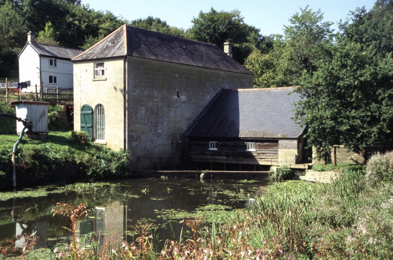
PLAN: the principal structure is a pumping station engine house, rectangular on plan and built on a former mill site with millpond adjacent to the west bank of the River Avon. There is a railway embankment to the west, under which the water pipes from the pumps feed the canal. Attached to the east, built across the mill race, is a wheel house, roughly square on plan. The engine house is arranged as three storeys to the south end and two storeys to the north. There are ground-floor doors to the end elevations of the engine house as well as a second floor door to its west flank.
EXTERIOR: the pump engine house is set forward of the wheel house, and has finely-tooled ashlar elevations under a hipped roof. It has round-arched openings to the ground floor and the openings to the upper floor have casements with square heads. Its south elevation faces the mill pond and has a plank door with strap hinges to the ground floor and a casement above. The west elevation has three ground-floor openings (the right has an altered cill and an extruding pump outflow pipe to an engineering brick opening in the railway embankment) and casements to the upper floor. There is an inserted door to the upper floor that is served by a C20 steel staircase and platform with an infilled area below, and there are modern steel stairs to the ground floor. The north elevation has a plank door to the right and a window to the left. The hipped roof has an ashlar stack.
Attached to the east elevation is the wheel house. The east elevation is of ashlar and has three round-arched openings with timber braced and ledged plank doors. The central opening has double-leaf doors and of slightly lower height than those to either side. The north and south elevations are weatherboarded and there are two casements to the north elevation. The wide pitched roof is covered in slate and there are repairs in engineering brick below the eaves. To the south the lower section of the east wall extends to form a cutwater and sluice. The wall is connected to filter grilles that traverse the millpond at the southern approach to the mill wheel, and have a central stone cutwater. To the north, the lower walls to the wheel house extend to form pound walls with coping stones. The east wall terminates with an ashlar flood arch facing north. The west wall extends further in random rubblestone with copings.
INTERIOR: the ground floor of the engine house is accessed from the north door with three stone steps down to the floor of the pit wheel room. The rectangular double-height room has the pit wheel set within its pit with cast-iron gear mounted on a shaft with overhung cranks and a flywheel. Attached to the crankpin are connecting rods that link to two 18’6” Boulton & Watt steam engine type beams in the room above. The rods pass through openings in the upper floor structure, which has oak beams and joists of large scantling and an inserted I-beam of 1888 date. A lateral stone engine wall spans the room at the south end with an arched opening to the pumps. Fixed to the wall above the arch is the mid-C19 foundry pattern used for the casting of the central bearing to the waterwheel. Mounted on the west wall is a cast-iron half-wheel of 1810-13, formerly part of the waterwheel. At intervals the whitewashed walls are incised with dated inscriptions, marking the height of flood water levels. There are three openings in the east wall to the wheelhouse. The floors are laid with diamond setts.
Beyond the arch in the lateral wall is the pump room with two pumps each with a pump rod and Watt linkage above connecting the south end of each Boulton & Watt beam. In the corner of the room is an 1840s piston head. The roof of the room has been adapted with late-C19 steel beams. Below water level is a pump inlet valve in the east wall. A timber stairway accesses a floor above with the Watt linkage which has attached C20 safety modifications. The pump outlet exits the building through the base of a west wall opening. A further flight of stairs leads to the upper floor at beam level with an exposed king-post oak truss roof. At the north end of the floor is a separate ‘mess room’ with a stone fireplace with cast-iron stove.
The wheelhouse has a wide-span, arch-braced oak roof with some adaptions including iron strap strengthening. There is a timber plank floor alongside the water wheel to three sides. The waterwheel is in two sections and constructed of 12 cast-iron half-wheels bolted together and secured on an axle shaft with wedges. The shaft runs in three gun metal bearings and the wheel rims have modern timber starts (spokes), float and seal boards. By the south wall, set within a plank platform are the upper mechanisms to the four control (depressing) sluices below. The elm depressing sluices were repaired in the mid-C20 and given concrete replacement lower members. The waterwheel is connected to the pit wheel by a semi-flexible coupling.
The Kennet and Avon Canal was built between 1794 and 1810, linking waterways between the River Thames at Reading and the River Avon at Bristol. Engineer John Rennie (1761-1821) was engaged and his designs for the canal included engineering solutions for the supply of enough water to serve the canal across the geologically porous and hilly terrain. Technical and legal problems were encountered as construction progressed, and led to alterations to the route and engineering methods. Close to the completion of the locks at Bath in 1804 it became apparent that the feeders in use would be insufficient for lockage requirements. In September 1804 the Canal Company Committee considered a number of options before deciding to build a relatively cost-effective water-driven pumping station at Claverton Mill, designed by Rennie. The pumps would use water mill technology with steam engine type beams to pump water from the river to the canal, a height of 14.6m (48 feet). However, the purchase of the grist mill on the site was the subject of lengthy legal discussions with the owner. This was eventually resolved and an agreement for Patrick O’Brien to supply masonry for the project was agreed in December 1809. Building work for the pumping station was completed in October 1810, although the machinery was subject to further delays. The fitting out of the plant, including pipes supplied by Fox & Co.’s Neath Abbey Ironworks, took place during 1811 and 1812 and the pumping station was operational by March 1813.
Although much of the original pumping plant remains in situ, extensive modifications were necessary from a relatively early stage to maintain and improve the water pumping function. The two large coupled waterwheels that power the pumps suffered from sagging and an internal system of cast-iron stays was introduced to try to address the problem. However, the stays regularly broke and the wheels were “constantly under repair” in 1843. Harvey & Co. of Hayle carried out strengthening works including bolts and shackles in 1844. At the same time they supplied and fitted Harvey & West double-beat valves to the pumps, replacing the original bucket pumps and butterfly valves. Problems with the wheel continued and repairs were regularly carried out until a centre bearing was fitted in May 1858, which finally addressed the waterwheel problems in the long term.
The pumping station had come under the ownership of the Great Western Railway Company in 1852, and the company carried out regular maintenance and repair to the pumps and other plant until nationalisation in 1948. The pumping station was operational until 1952, when it was taken out of use and a centrifugal pump powered by a diesel engine was installed to maintain a minimum water level in the canal. The pumping station was restored in 1969-75 and has been maintained since that time, with electric pumps having been installed to serve the canal as part of a restored waterway that is under the care and management of The Canals and Rivers Trust.
Claverton Pumping Station, Bath is listed at Grade I for the following principal reasons:
Architectural interest:
* as one of the few early-C19 beam pumping stations to function in its original use Claverton is a remarkable survival;
* it is the only working example of a waterwheel-driven pumping station on the national canal network, and is of international significance and exceptional interest;
* very few canals retain their original pumping stations in working order. Those that survive well with machinery are listed at a higher grade;
* it utilises innovative technology including the parallel motion linkage, invented by James Watt;
* as a neatly-designed early-C19 pumping station and wheelhouse it is well-built using local Bath stone and timber roof structures in the vernacular traditions of the period;
* despite the requirement for adaptation and maintenance over two centuries of use the principal elements of C19 equipment, including beams and pumps survive well.
Historic interest:
* John Rennie was one of our greatest civil engineers . His few major structures to survive well include Lancaster Canal Lune Aqueduct, Dundas Aqueduct and Crofton Pumping Station (all Grade I);
* the design and function of the equipment combines timber-framed construction methods with innovative industrial design; as such it retains rare evidence of the transition in construction techniques that took place at this point in the Industrial Revolution.
Group value:
* as part of a complete historic set of canal structures including nearby related Grade II listed buildings and other key structures listed at a higher grade.
External links are from the relevant listing authority and, where applicable, Wikidata. Wikidata IDs may be related buildings as well as this specific building. If you want to add or update a link, you will need to do so by editing the Wikidata entry.


Other nearby listed buildings