Approximate Location Map
Large Map »
Latitude: 53.7069 / 53°42'24"N
Longitude: -0.45 / 0°26'59"W
OS Eastings: 502412
OS Northings: 424501
OS Grid: TA024245
Mapcode National: GBR TT9K.CX
Mapcode Global: WHGFX.2301
Plus Code: 9C5XPH42+Q2
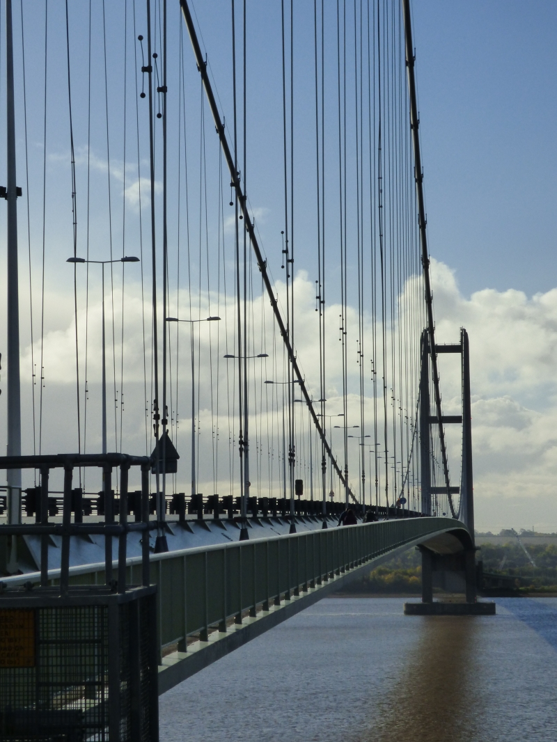
Entry Name: The Humber Bridge
Listing Date: 12 July 2017
Grade: I
Source: Historic England
Source ID: 1447321
ID on this website: 101447321
Location: North Lincolnshire, DN18
County: North Lincolnshire
Civil Parish: Hessle
Built-Up Area: Hessle
Traditional County: Lincolnshire
Lieutenancy Area (Ceremonial County): East Riding of Yorkshire
Tagged with: Suspension bridge Road bridge
Suspension Bridge. 1973 to 1981. Built for the Humber Bridge Board; consulting engineers Freeman Fox & Partners with Bernard Wex partner-in-charge, consultant architect R E Slater; main contractors for superstructure British Bridge Builders Ltd (consortium of Sir William Arrol, Cleveland Bridge and Engineering, and Redpath Dorman Long); main consultants for substructure and towers John Howard & Company Ltd. The administration building, garages and stores arranged round a maintenance store on its east side, toll booths and associated canopies are not included in the listing.
Suspension Bridge. 1973 to 1981. Built for the Humber Bridge Board; consulting engineers Freeman Fox & Partners with Bernard Wex partner-in-charge, consultant architect R E Slater; main contractors for superstructure British Bridge Builders Ltd (consortium of Sir William Arrol, Cleveland Bridge and Engineering, and Redpath Dorman Long); main consultants for substructure and towers John Howard & Company Ltd. The administration building, garages and stores arranged round a maintenance store on its east side, toll booths and associated canopies are not included in the listing.
MATERIALS: reinforced concrete, steel panels, high tensile steel wire cables.
PLAN: suspension bridge with a deck carrying a dual two-lane carriageway with footpaths and cycle tracks. The north, Hessle tower stands on a concrete pier located on land on the high water line. The south, Barton tower stands on a concrete pier in the water, supported on twin hollow, circular caissons. At either end of the bridge are massive, rectangular anchorages for the bridge cables.
DESCRIPTION: the bridge has two concrete towers each with tapered, hollow legs and four horizontal, portal beams; the lowest beam is situated immediately beneath the road deck. The corners of the legs and beams are rounded and the slip-formed construction technique means that there is a lack of obvious joints. The legs contain maintenance lifts and access ladders. The north, Hessle tower stands on a reinforced concrete slab 44m long by 16m wide and 11.5m deep, founded about 8m down in the chalk. The south, Barton tower stands on a concrete pier about 16m deep supported on twin hollow circular caissons, each 24m in diameter, that penetrate into the Kimmeridge Clay to a depth of 8m.
At both ends of the road deck are massive, concrete anchorages. Above ground, the side walls of the anchorages comprise five inclined and projecting blocks, giving a stepped profile. The blocks are decorated with inclined bands of narrow, projecting concrete ribs. The inner and outer faces of the anchorages are decorated with horizontal, projecting blocks. Inside, each anchorage contains two chambers where the main cables are supported by steel saddles before splaying out into separate strands that fit over strand shoes which are retained by pre-stressed rods into the anchor blocks at the backs of the chambers. The 190,000 tonne anchorage on the north bank is 65.5m long by 36m high and founded about 21m below ground level. The 300,000 tonne anchorage on the south bank is similar, but supported on a cellular structure built within a frame-work of diaphragm walls founded 35m below ground level in the Kimmeridge Clay.
The road deck is formed of 124 streamlined, hollow box sections built of stiffened steel plate panels. The box sections are 22m wide and 4.5m deep with 3m wide panels along each side which are lower than the road carriageway and cantilever outwards to carry the footpaths and cycle tracks. The carriageway has outer and central crash barriers formed of four horizontal, high-tensioned steel cables bolted at regular intervals to rectangular, steel posts. The angled sides to the carriageway contain small, oval inspection hatches. The outer edges of the footpath and cycle track have steel handrails with closely spaced tubular railings. Slung beneath the road deck is a movable, maintenance gantry which is no longer in use.
Each main cable of the bridge comprises 37 strands, each of 404 wires, with an additional 800 wires to the cables above the north side span. The cables are strapped and wrapped, with hanger clamps fixed at regular intervals onto which the 242 high tensile steel hangers supporting the road deck are attached. Dehumidifiers have been added to the cables to combat corrosion.
Tentative bridge schemes crossing the Humber were first put forward in the 1860s, but the first major crossing proposal was a tunnel scheme in 1872-73 which was not built because the geology and topography of the area made construction costs excessive. In 1928 the City and Corporation of Hull again investigated the feasibility of a crossing. Sir Ralph Freeman, later of Freeman Fox & Partners, was retained to examine tunnel and bridge alternatives and proposed a multi-span road bridge. The national economic crisis in 1931 forced its abandonment, but there had already been fierce opposition to the multiplicity of river piers required and effects this would have on the shifting river bed and navigable channels. Inspired by the Golden Gate Bridge, Freeman realised the force of the opposition’s arguments would be removed if the bridge could cross the river in a single span. However the scheme was shelved due to the commencement of the Second World War.
In 1955 Sir Gilbert Roberts, also of Freeman, Fox & Partners, prepared a comprehensive report proposing a 4,580ft (1,396m) suspension bridge. This led to the Humber Bridge Act being passed in 1959, and the creation of the Humber Bridge Board. The Act gave the Bridge Board powers to construct the bridge, but withheld the power to raise the necessary money. Then in 1969 a government sponsored report entitled ‘Humberside - A Feasibility Study’ was prepared by the Central Unit for Environmental Planning in the Department of Economic Affairs. It recommended that the bridge be built to make possible the planned development of the Humberside region during the 1980s, a national perspective which embodied the bridge with regional aspiration and the desire for regional cohesion of a county only formed in 1974. While the City of Hull, natural capital of the county, embraced the bridge enthusiastically, envisaging it as a physical end to the city's perceived isolation, it was less welcomed elsewhere in the region, which failed to see its economic benefits. Nevertheless, on the strength of this report the government decided to lend the necessary finance to the Humber Bridge Board in May 1971 and detailed designs for the scheme could commence.
Freeman, Fox & Partners were confirmed as consulting engineers, with Bernard Wex as Partner-in-Charge and Mr R E Slater as consultant architect for the main bridge superstructure and approach roads. Freeman, Fox & Partners were well-known for their bridge construction around the world; they were responsible for a number of large-scale suspension bridges including the Severn Bridge between England and Wales (1961-66, Grade I, LE no 1119760), the Forth Road Bridge, Scotland (1958-64, Category A, LB47778), and the Bosporus Bridge, Istanbul, Turkey (1973).
The main contractors for the superstructure were the consortium British Bridge Builders Ltd comprising Sir William Arrol, Cleveland Bridge and Engineering, and Redpath Dorman Long: all had considerable bridge-building expertise and had contributed to the construction of both the Forth Road Bridge and Severn Bridge. The main contractors for the substructure and towers were John Howard & Company Ltd.
The resulting bridge has a main span of 1,410 metres, making it the longest bridge span in the world when built. The total length anchorage to anchorage is 2,220m; the challenges of the geology meant it is markedly asymmetrical, with side spans from the two towers of 280m on the north, Hessle side (sound hard chalk) and 550m on the south, Barton side (Kimmeridge Clay beneath boulder clay, gravel and soft alluvium, which turned to slurry on contact with water). The height of the two towers above the piers is 155.5m and the road deck is 30m above high water level to enable the passage of shipping beneath. The size of the bridge meant that the effect of wind upon the structure had to be carefully determined. Wind tunnel tests were carried out on models of the deck and towers at the National Maritime Institute, Teddington, to establish aerodynamic stability; the bridge is designed to withstand wind speeds of up to 105mph on the deck structure and 150mph at the top of the towers.
The towers were constructed of concrete, rather than steel like the Severn Bridge and Forth Road Bridge towers. This is the first use of concrete towers for such a large-scale bridge; previously the longest span suspension bridges with concrete towers were those at Tancarville, France (608m) and Lillebaelt, Denmark (600m). The towers consist of two hollow reinforced concrete legs braced by four horizontal portal beams. The concrete was slip formed (poured into a continuously moving form) using an operating platform which was raised by 48 hydraulic jacks, resulting in a smooth, un-jointed finish. The platform was designed to enable the two legs to be built simultaneously.
The deck used Freeman Fox & Partners’ innovative approach, first used for the Severn Bridge, of streamlined, hollow box sections with the upper flange covered in mastic asphalt to provide the roadway. The streamlined shape of the welded steel box sections was aerodynamically stable and lighter than traditional lattice type trusses. The 124 box sections were assembled off-site and moved to the bridge by river using pontoons, from which they were then winched into position, attached by inclined hangers to the main bridge cables, and finally welded together. Each weighed 140 tonnes and was built with cantilevered walkway panels and hand railings in place. The main cables were designed to withstand a load of 19,400 tonnes and each weighed 5,500 tonnes. They were constructed in-situ using the aerial spinning method where compacted bundles of wire strands were formed by looping wire between the anchorages. The cables were then strapped, coated in red lead paste and wrapped in galvanised iron wrapping.
From the outset, Freeman Fox & Partners advised the Humber Bridge Board that in addition to the engineering complexities involved, the scale of the bridge would have a major visual impact on the environment. In addition to satisfying engineering requirements and economy, an aesthetic approach was sought through the appointment of Mr R E Slater to advise on architectural aspects of the project with special reference to the structures. This resulted in the rounding of the corners of the tapered legs and the portal beams of the towers, the use of inclined concrete ribs on the vast side walls of the anchorages that depict their resistance to the pull of the cables, random block finishes to provide visual relief to the end walls of the anchorages, and the choosing of a colour for the suspended steel structure which complemented the natural environment and the concrete of the towers to produce a harmonious visual entity.
The approach roads, viaduct and car parks, and the administration building were carefully designed to complement the bridge. The toll plaza was situated on the Hessle side with the toll booths arranged obliquely across the road and covered by a protective canopy. The toll system was one of the most technically advanced of its time, being able to classify vehicles, calculate the toll and display it to drivers and collectors. The administration building (not included in the listing) stands adjacent to the plaza and was designed by architects’ practice Parker and Rosner.
Work began on the embankment for the south approach road in July 1972 with work beginning on the actual bridge in March 1973. It was opened to traffic in June 1981 and was officially opened by Her Majesty Queen Elizabeth II on 17th July 1981.
In 1995-98 the deck hanger clamps round the cables were replaced as part of routine bridge maintenance. In 2009 cable corrosion was discovered due to water penetration, a problem that also afflicted the Severn Bridge and Forth Road Bridge. A cable dehumidification programme began in December 2009 and was completed in January 2011. Pressurised dry air is blown through the cables, absorbing moisture and bringing down the relative humidity from 90 per cent to 40 per cent. An acoustic monitoring system was also installed. In 2014-15 the toll booths and protective canopy were replaced with new booths and canopies. A new electronic tolling system has also replaced the earlier system.
The Humber Bridge of 1973 to 1981, built for the Humber Bridge Board, consulting engineers Freeman Fox & Partners, is listed at Grade I for the following principal reasons:
ARCHITECTURAL INTEREST:
* Design: as a sublime, landmark bridge demonstrating an exemplary pairing of functional engineering with aesthetic quality to produce a bridge of great sophistication and integrity;
* Engineers: the bridge marks the zenith of Freeman Fox & Partners bridge-building prowess as a British civil engineering firm specialising notably in large-scale suspension bridges including the Forth Road Bridge, Severn Bridge, and Bosporus Bridge in Istanbul;
* Aesthetic Quality: the inclusion of a consulting architect on the design team resulted in a taut, pared-down elegance, which from a distance almost belies the bridge’s extreme size and strength, and produces a visual harmony which enables it to sit intimately within the landscape it occupies;
HISTORIC INTEREST:
* Engineering First: when completed in 1981, the Humber Bridge had the longest single bridge span in the world at 1,410 metres, a record it impressively maintained for another 16 years, and even now it remains in the top ten longest spans worldwide;
* Technological Innovation: the use of reinforced concrete to construct the towers was the first time that concrete had been used for such a long span suspension bridge, towers for such bridges having previously been made of steel as for the Forth Road Bridge and Severn Bridge.
External links are from the relevant listing authority and, where applicable, Wikidata. Wikidata IDs may be related buildings as well as this specific building. If you want to add or update a link, you will need to do so by editing the Wikidata entry.


Other nearby listed buildings